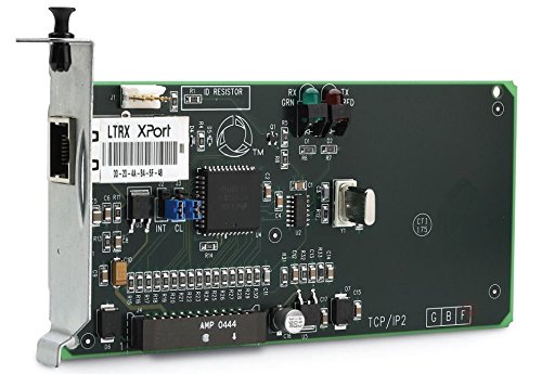
How to Install a TLS-3XX Console/RedJacket ProPlus Pro Max TCP/IP Interface Module.
Posted by Alex Ortega on August 24, 2022
Please refer to Veeder Root Manual No: 577013-776 l Revision: F.
Tank Overwatch shall not be liable for errors contained herein or for incidental or consequential damages
in connection with the furnishing, performance, or use of this publication.
This guide contains procedures to install a TCP/IP Interface Module into the following consoles:
• Veeder-Root TLS-3XX consoles
• Red Jacket ProPlus and ProMax consoles
Alright lets get to it.
1.TCP/IP Interface Requirements.
2. Installation of the TCP/IP Interface Module.
3. TLS Console Setup of the TCP/IP Interface Module.
1. TCP/IP Interface Requirements.
Minimum system requirements for TCP/IP Interface Module operation are listed below:
• Console system software: Version 15 or higher - Version 21 or higher is recommended.
• Network connection to a PC requires a hub. Connecting to a hub requires a straight CAT 5 cable.
• Direct connection to a laptop requires an ethernet crossover cable.
• Connection to a LAN or WAN.
• Knowledge of networking.
TCP/IP Kits
• TLS-300/ProPlus console kit (P/N 330020-424):
- Installation Guide (P/N 577013-776)
• TLS-350/ProMax console kit (P/N 330020-425):
- Installation guide (P/N 577013-776)
Notice*
330020-424 includes the screws. 330020-425 includes the wiring harness.
Example of a TCP/IP Interface Module P/N 330020-424
2. Installation of the TCP/IP Interface Module.
Installation of the TCP/IP Interface module consists of:
1. Verifying the module’s configuration
2. Installing the module in the TLS-300 console or the TLS-350 console
3. Performing setup of the module in the TLS
Verifying TCP/IP Interface Module Configuration
Key components of the TCP/IP Interface module are shown in Figure 1.
Key components of the TCP/IP Interface module are shown in Figure 1. IMPORTANT! Write down the ethernet address from the label on the back of the TCP/IP board. You will need to enter this number for the TCP/IP board’s hardware address in the module’s IP Address/Configuration procedure later in this manual (also record the rev of the board as it may also be needed).
Fig.1
Installing the TCP/IP Interface Module in the Console
TLS-300/PROPLUS CONSOLES
1. Open the left door of the console (see Figure 2). Verify that the battery backup switch is in the On position, then turn Off power to the console.
2. Remove the knockout blank from the left bottom of the console. Slide in the configured TCP/IP Interface Module until the motherboard connector is snugly seated and the left edge of the module’s bracket is in the notch cutout in the left side of the console. Attach securing screw from kit (see Figure 3). Leave the console door open.
Fig.2
TLS-350/PROMAX SERIES CONSOLES
1. Open the left door of the console. Verify that the battery backup switch (SW1) is in the ‘On’ position (see Figure 4), then turn off power to the console.
Fig.4
2. Installing the TCP/IP module in slots 1 - 3 (Preferred Location)
The TCP/IP module can be installed in any empty slot of the Comm bay card cage, but the module’s default settings require that it be installed in slots 1 - 3.
If your console has a snap connector which secures the cover plate in the card cage, pull it out and lift out the cover plate. If your console has “knockout” cover plates, open the printer door and insert a flat blade screw driver in the slot provided in the front of the cover plate you are removing and twist it to break the front set of metal securing tabs (ref item 2 in Figure 5). Once the front tabs are broken, carefully move the loosened end of the plate up and down until the rear set of securing tabs break. Remove and discard the cover plate. Slide the module into the open slot until the motherboard connector is snugly seated. Do not apply excessive force when installing the module. With your thumb, push in the black retaining fastener on the end plate until it snaps into the hole in the card cage.
Fig.5
3. Installing the TCP/IP module in slot 4 (Alternate Location)
If slots 1 - 3 are in use, or if you want to free up slots 1 - 3 for other modules, the TCP/IP module can be installed in slot 4. To use slot 4, you must move jumpers J2 and J3 on the module onto the 2 top pins, and connect the cable from the kit (P/N 330020-425) to connector J1 on the TCP/IP module and to connector J6 on the console’s ECPU board (see Figure 6).
Notice* If the TCP/IP module is installed in slot 4, the displayed slot number (X) will be 5.
4. Verify that the RJ-45 plug in the module’s bracket is accessible through the slot opening in the bottom of the
console
5. When you are finished, make sure any unused slots in the Comm cage have a blank end plate installed. Leave the console door open.
Fig.6
3. TLS Console Setup of the TCP/IP Interface Module
1. Close and secure the console front door. Restore power to the console.
2. You will need to know what version of software is installed in the console to properly set up the TCP/IP module. Press the front panel MODE key to access Diag Mode. Press FUNCTION key to access System Diagnostic:
Press the STEP key to view the software revision level:
3. Press the front panel MODE key to access the Setup Mode. Press the FUNCTION key to access Communications Setup.
4. In Communications Setup, press STEP until you see Port Settings, then press ENTER to display the message::
If necessary, press the TANK/SENSOR key until you see the message above, where X = the slot number in which you installed the TCP/IP Interface Module, and Type = S-SAT.
NOTICE: For TLS-350/ProMax consoles only - if the TCP/IP module was installed in slot 4 of the
Comm Bay card cage, the displayed slot number (X) will be 5.
5. Depending on displayed board type (S-SAT) and the console’s installed software revision level, select the Comm board setup parameters shown in Table 1 or Table 2 as applicable.
Table 1. Comm Setup Selections - S-SAT board type & V15 - V20 console software
Comm Setup Parameter |
Setting |
Baud Rate |
9600 |
Parity |
NONE |
Stop Bit |
1 STOP |
Table 2. Comm Setup Selections - S-SAT board type & V21 & later console software
Comm Setup Parameter |
Setting |
Baud Rate |
9600 |
Parity |
NONE |
Stop Bit |
1 STOP |
Data Length |
8 DATA |
Code (security) |
DISABLED |
DTR Length |
HIGH |
RS-232 END OF MESSAGE |
DISABLED |
Posted by Alex Ortega on August 24, 2022